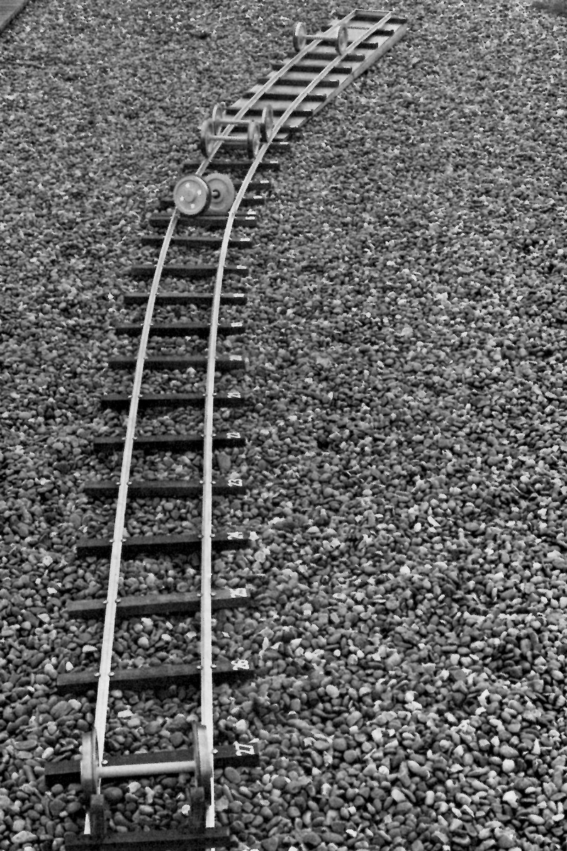
Figure 1. Model railway track, also showing the results of the experiments with various wheelsets. See also Figure 3.
When George Stephenson began the engineering work on the Stockton and Darlington railway in 1821 he was already familiar with the use of coned and flanged iron wheels running on iron rails. He knew that these coned wheels gave rise to lateral oscillations, oscillations which have bedevilled railway engineers ever since. Fortunately, for the speeds of George Stephenson's day and for those of the following century, empirical and evolutionary development was able to ameliorate the results of the lateral oscillations so that the riding of railway vehicles reached an acceptable standard. More recently, as train speeds and weights have increased dramatically, the consequences of the lateral oscillations have become more serious. For example, at certain speeds a sustained lateral oscillation of a vehicle, which is termed hunting, can occur. In spite of the track being perfectly straight the wheels oscillate so that they move across the rail from one flange to the other and every time the flange strikes the rail forces are induced which can cause damage to both vehicle and track and there can be, at least, discomfort to the passenger and, at worst, the risk of derailment.
Hunting prevents safe and economic operation at high speeds and hence was a major technical obstacle to the development of high speed trains. Moreover, at ordinary speeds the prevention of hunting can make a significant contribution to better passenger comfort and to reduced operating costs.
When the work that is to be described in this article was started there was little scientific understanding of the hunting problem and no adequate theory which could be used in the design of railway vehicle suspensions. The solution of the hunting problem and the emergence of a practical theory of railway vehicle dynamics has led the way towards projects like the Advanced Passenger Train. To see why, we must first look at some fundamentals and then we must look at how these fundamentals are applied.
Figure 1. Model railway track, also showing the results of the experiments with various wheelsets. See also Figure 3.
The wheelset is the most basic component of a railway vehicle. In the conventional wheelset, two wheels are rigidly mounted on a common axle. Each wheelset has a coned, or otherwise profiled, tread and a flange on the inside of the rail. A flangeway clearance is provided so that the wheelset can move laterally within a distance of about ±7 mm before flange contact occurs.
This type of wheelset has a long history. It seems to have been developed by a process of trial and error during the eighteenth and early nineteenth centuries. The details of this development have been obscured by the mist of time but we can illustrate, with some simple experiments, why the wheelset has the form it has. These experiments show the influence of the shape of the tread on the running of a wheelset. The track, Figure 1, is curved and slightly inclined so that wheelsets can roll down towards the end following release at the top.
The first wheelset has cylindrical treads with inside flanges, Figure 2(a). Upon release it rolls very smoothly down the straight part of the track, but it doesn't negotiate the curve properly. The flange runs into the curve and guidance is only achieved by brute force and much friction.
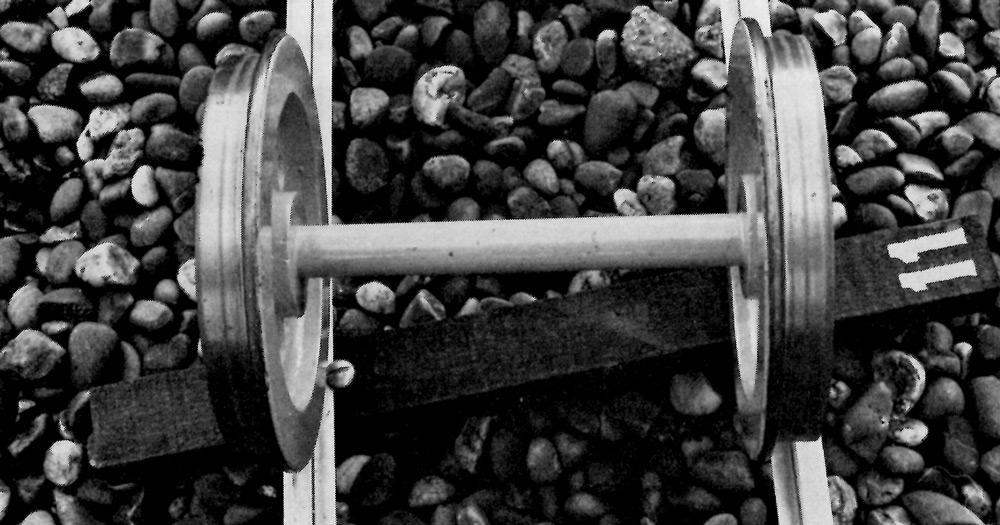
Figure 2. Model wheelsets: (a) wheelset with cylindrical treads and inside flanges.
The second wheelset, shown in Figure 2(b), has cylindrical treads with flanges on the outside. Whilst again it runs very smoothly down the straight, its behaviour on the curve is even worse than the first wheelset.
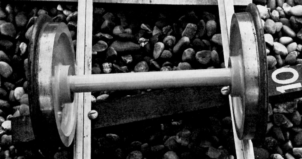
Figure 2(b). Wheelset with cylindrical treads and outside flanges.
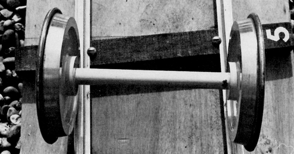
Figure 2(c). Wheelset with outside flanges and purely coned treads.
The third wheelset, Figure 2 (c), has outside flanges and purely coned treads. But the coning is in the opposite sense to that usual. Upon release, this wheelset merely runs off at angle until flange contact is made, even on the straight.
The fourth wheelset, Figure 2 (d), has inside flanges and coned treads. It is, therefore, similar to a conventional wheelset - except that it does not have a solid axle. The axle allows the wheels to rotate independently. Upon release it rolls along the track for a short distance, hesitates, takes up a large yaw angle and derails.
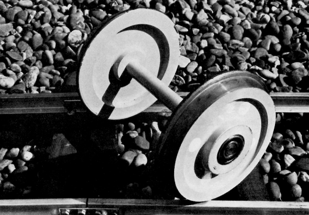
Figure 2(d). Wheelset with inside flanges, purely coned treads but with independently rotating wheels.
Finally, the fifth wheelset, Figure 2 (e), has inside flanges, coned treads and a rigid axle. It is a conventional railway wheelset. Upon release, it rolls quite freely all the way to the end of the track. But a closer look reveals that there is something else quite significant about the motion. As it rolls along the track there is a weaving motion from side to side.
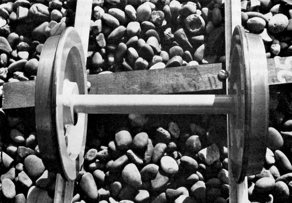
Figure 2(e). Conventional wheelset with inside flanges, coned treads and rigid axle.
The results of these experiments are summarized in both Figures 1 and 3 which show how far each wheelset managed to travel. They show that the ingredients for success are a wheelset with a solid axle, coned treads and inside flanges. These results, of course, are consistent with the experience of the early railway engineers. In fact, the coning was apparently introduced, not with the object of guidance through curves (though its potential advantage in this respect was recognized later), but simply to prevent the almost constant rubbing of one or other flange against the rail which led to rapid and unacceptable wear. Similarly, the flangeway clearance was opened out to achieve the same purpose.
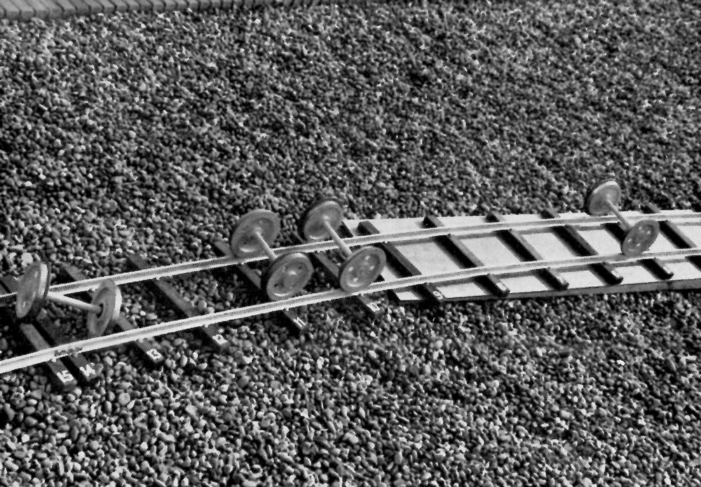
Figure 3. Another view of model railway track showing how far each wheelset managed to travel. The coned wheelset with inside flanges reached the end of the track but the other wheelsets stopped in order from left to right (d) (derailed), (a), (c) and (b).
A further most significant result of our simple experiments was that good guidance was obtained at the cost of a degree of lateral oscillation. There is a fundamental trade-off between guidance and stability.
Another important point is that the shape of the treads determines the type of motion to a far greater degree than the form of flange. This can be illustrated by the next series of experiments. In these, we use greatly simplified wheelsets, in which the flanges have disappeared. Firstly, upon releasing the cylinder it rolls down the track in a perfectly straight line, Figure 4(a). No lateral oscillation but no guidance either. Secondly, the inverse cone, Figure 4(b), runs off the track and is completely unstable.
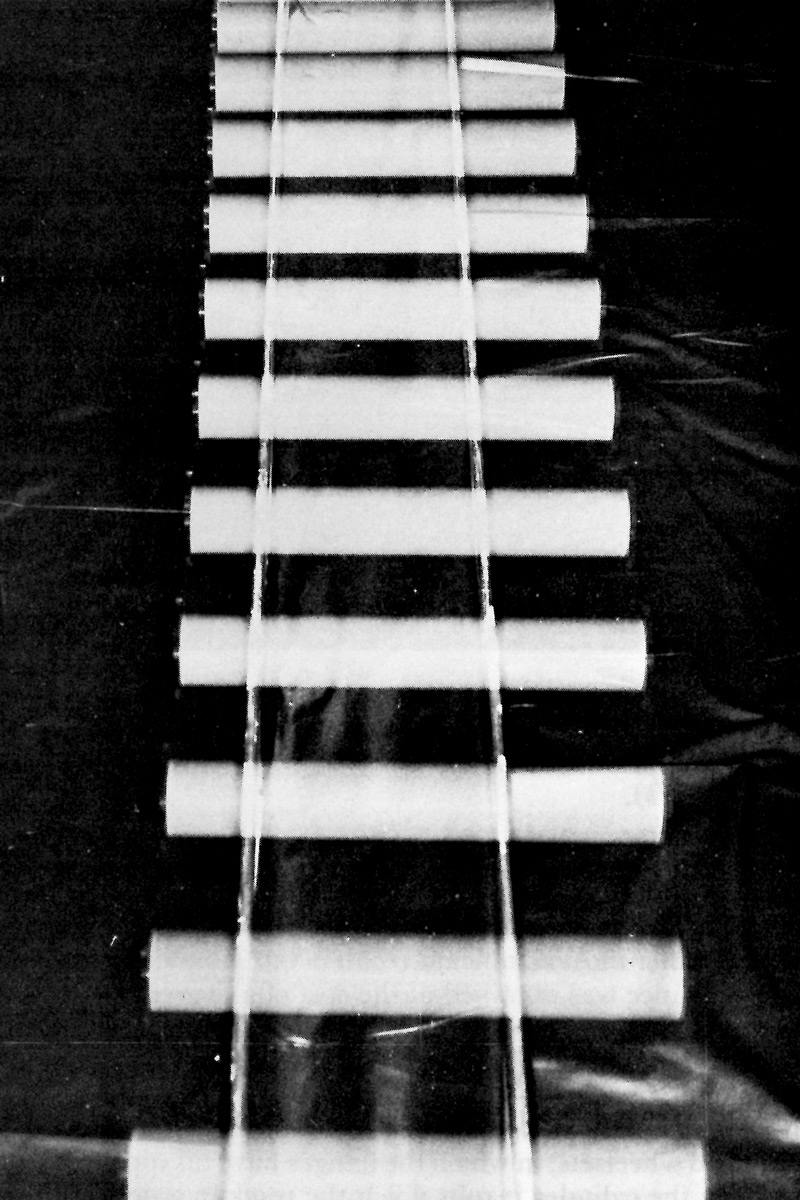
Figure 4. Experiments showing influence of tread shape: (a) cylinder.
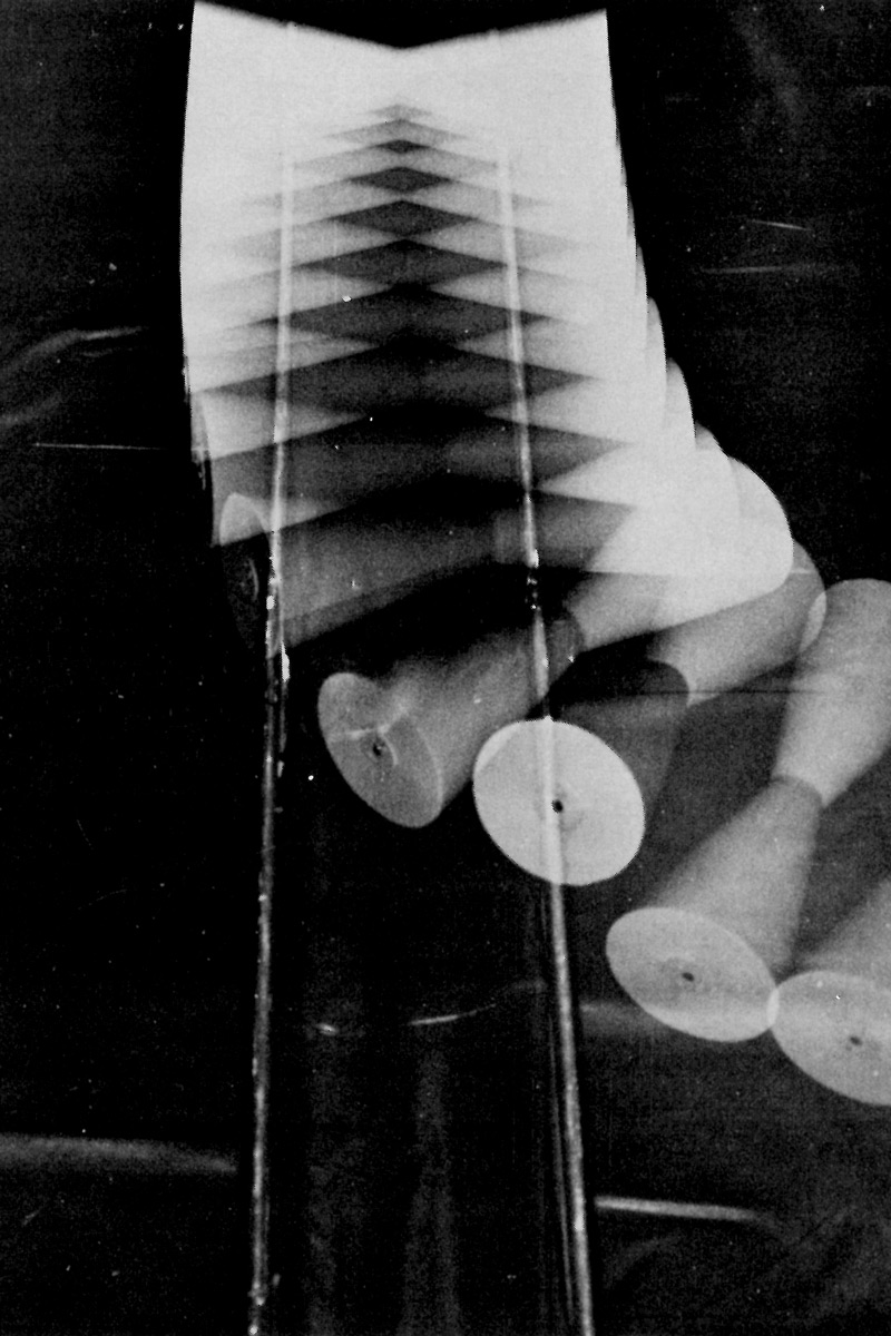
Figure 4(b). Inverse double cone.
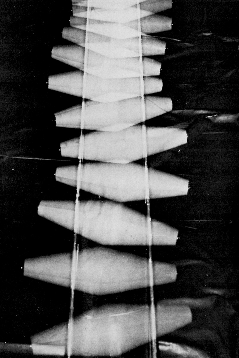
Figure 4(c). Dicone.
Finally, the dicone rolls down the track very smoothly, following the track, but weaving as it goes, Figure 4(c).
It is clear from the experiment with the dicone why it is that a coned wheelset can steer. If, as the wheelset is rolling along the track, it is displaced slightly to one side, the wheel on one side is running on a larger radius and the wheel on the other side is running on a smaller radius. Because the wheels are mounted on a common axle one wheel will move forward faster than the other because its instantaneous rolling radius is larger. Hence, if pure rolling is maintained, the wheelset moves back towards the centre of the track - a steering action is provided by the coning. However, the wheelset overshoots the centre of the track and the result is the weaving oscillation seen in the experiments.
On a curve it is possible for a coned wheelset to roll round the curve, by simply moving outwards so that the two rolling circles fit a cone with its apex at the centre of the curve. This is illustrated in Figure 5. This would be impossible for wheels with cylindrical treads without skidding, unless the wheels were independently mounted.
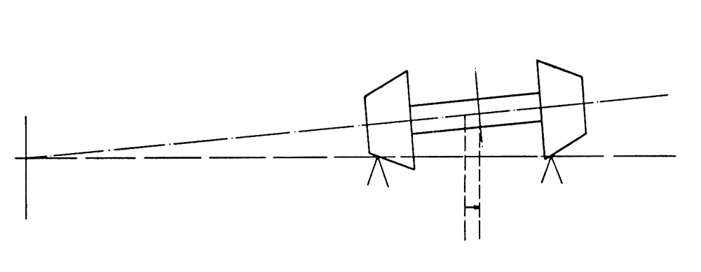
Figure 5. Rolling of wheelset with coned treads round uniform curve.
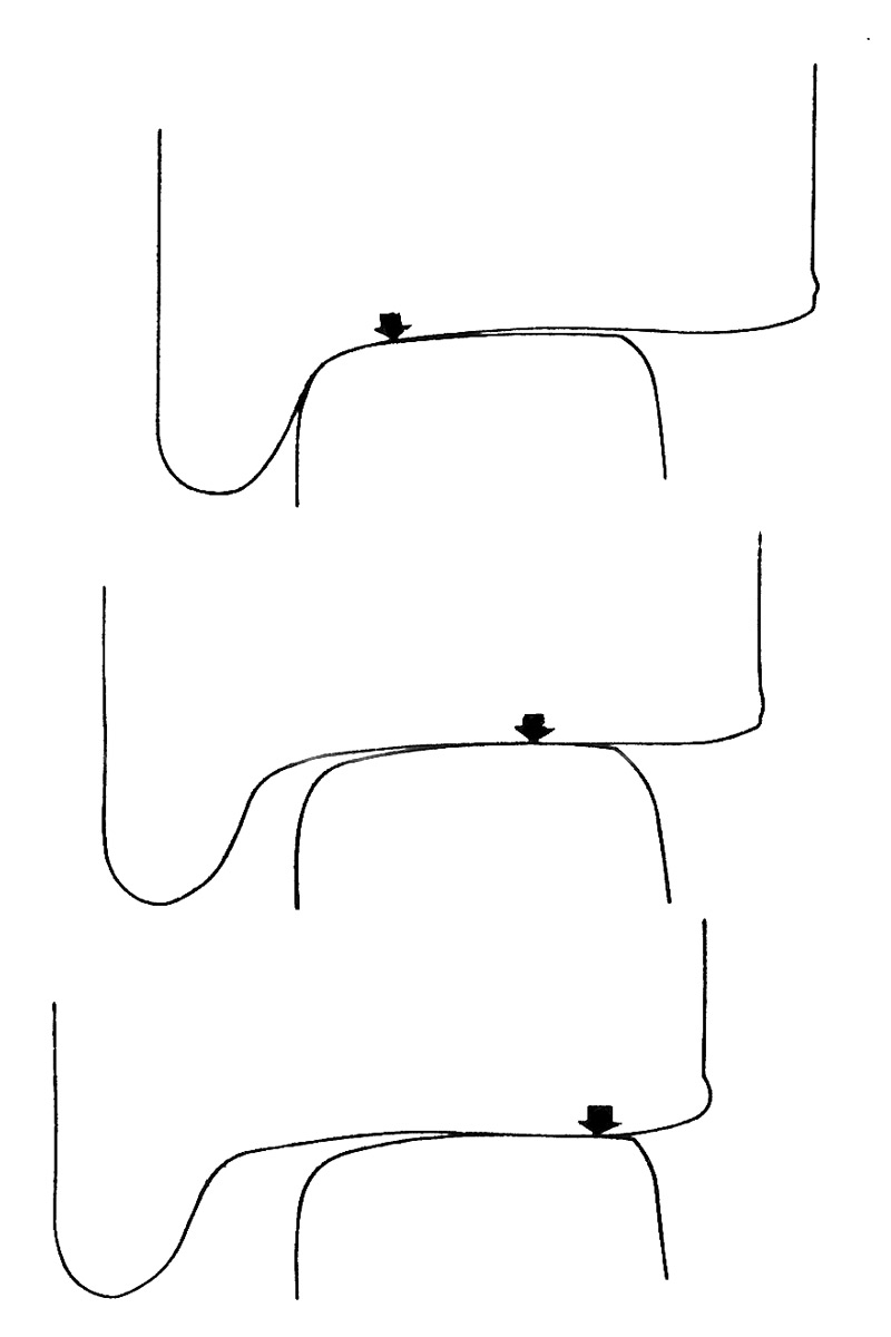
Figure 6. The geometry of worn wheels rolling on worn rails. The arrow indicates how the point of contact moves across the rail-head as the wheelset is displaced within the flangeway clearance.
In practice, wheelsets do not have purely coned wheels for long because of wear. There are, in any case, a number of advantages in a hollow tread profile and so the wheel-rail geometry is often as shown in Figure 6. Nevertheless, the wheelset works in exactly the same way as one with purely coned wheels except that the effective cone angle is then much larger than is usual for a coned wheel. The geometry is complex, as can be seen from the figure and a computer is used to analyse it.
So far, I have considered the implications of the geometry of the wheel and rail combination. I have done this, making two important assumptions which are not strictly true. Firstly, I have assumed that pure rolling takes place. Secondly, I have assumed that both wheels and rails are rigid. In reality, pure rolling occurs only rarely because of the action of creep or microslip (not in any way associated with the creep of metals at elevated temperatures). When an elastic body, such as a wheel, rolls over another elastic body, such as a rail, contact takes place over an area rather than at a point. Creep arises from this elasticity of the wheel and rail in the vicinity of the area of contact.
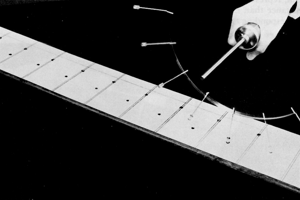
Figure 7. Demonstration of longitudinal creep using a wheel with the flexibility of the tread artificially exaggerated and represented by spokes. The wheel is travelling from left to right. On the far side, the wheel rolled with no torque applied to the axle and so the spokes lined up with the transverse marking on the track. On the near side, torque is applied, the spoke deflects when in contact and there is a discrepancy between the points at which contact is made by the spokes and the transverse marking on the track, which increases with distance travelled.
I can demonstrate what I mean by creep by means of this model wheel, Figure 7. It has the elasticity of its rim artificially exaggerated, by means of the flexible spokes. Now if I roll the wheel without applying any torque or force, the lines on the surface on which it is rolling line up with the points on the rim. But if, as I roll the wheel forward, I apply a torque, as if the wheel were being driven by a motor, then we see continuous deformation of the rim, represented by the spokes, and the wheel moves through a shorter distance than expected. The fractional difference between the distance corresponding to the number of revolutions of the wheel multiplied by the perimeter of the wheel and the actual distance travelled is called the creepage and the whole process is called longitudinal creep.
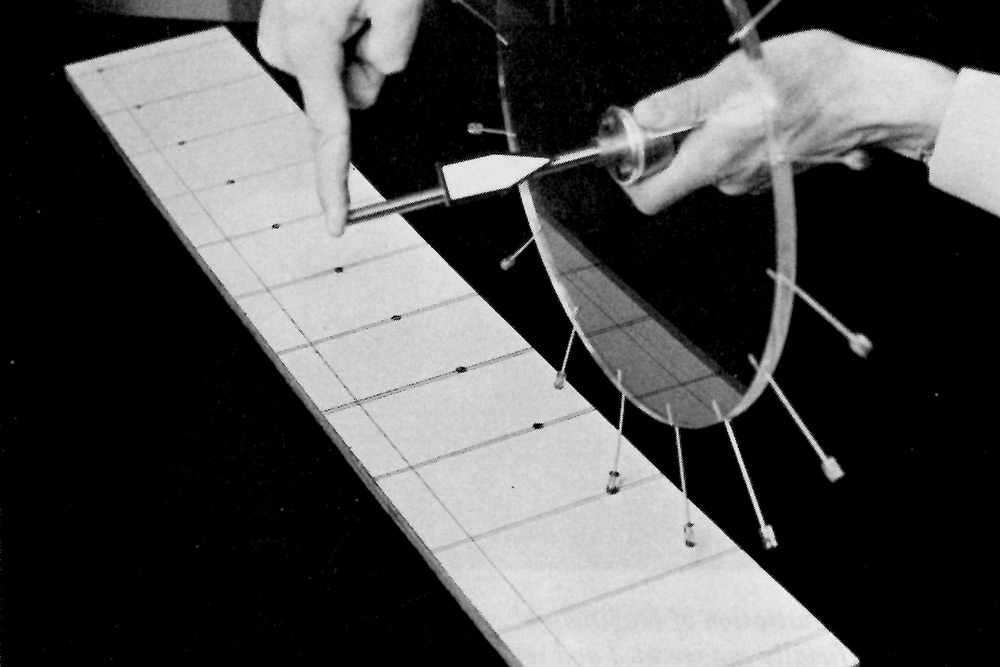
Figure 8. Demonstration of lateral creep using the special wheel. In this case as the wheel moves from left to right, though the plane of the wheel remains parallel to the line on track, it drifts laterally because a transverse force is being applied to the wheel.
Similarly, the rim of our simplified wheel can deflect laterally. If I apply a lateral force to the wheel, Figure 8, as I roll it along then, even though the wheel is pointing in the forwards direction parallel to the line on the surface, the wheel will drift across the surface, its path making an angle with the 'forwards' direction. This is lateral creep and the angle is a measure of the lateral creepage. Physically, the process is similar to the 'slip' of a pneumatic tyre under the action of a cornering force in the case of a road vehicle. In the case of the railway wheel the creepages are small but nevertheless important, as I shall show later.
Figure 9 is a plot of the creep force against the creepage. For zero force there is zero creepage and pure rolling. As the force is increased, elastic deformation of the rim occurs with consequent creepage, and the creepage is directly proportional to the force applied. For the lateral oscillations of wheelsets this linear portion of the plot is of prime interest. With further increases of force, the force approaches the level of sliding friction and then sliding of the wheel occurs. So creep is a mode of progression intermediate between pure rolling and pure sliding.
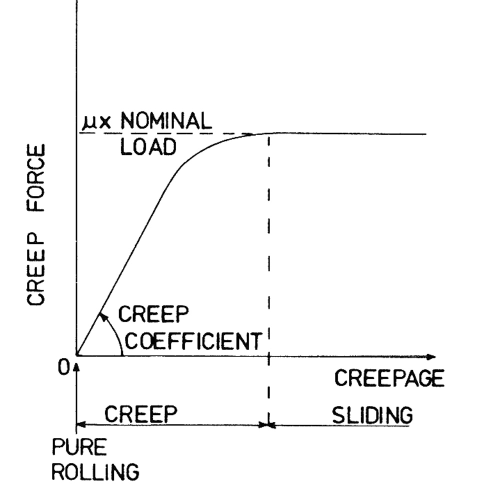
Figure 9. The relationship between creep force and creepage showing the three regimes of pure rolling, creep and pure sliding.
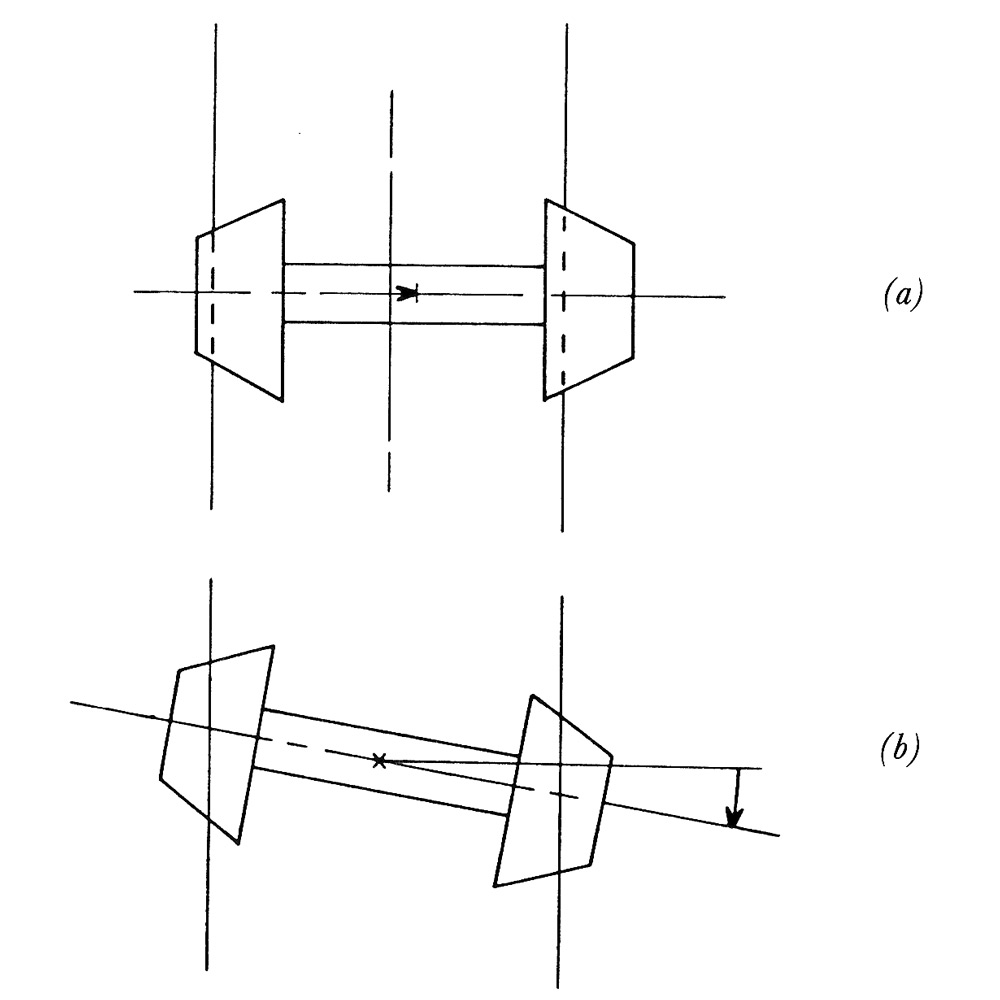
Figure 10. The two degrees of freedom of a single, isolated wheelset (a) lateral translation (b) yaw or rotation about a vertical axis.
Having introduced the phenomenon of creep let me return to the dynamics of a wheelset. A wheelset running along the track at constant speed has two degrees of freedom. It can move laterally within the flangeway clearance, and it can yaw or rotate about a vertical axis, Figure 10. The creep mechanism ensures that when a wheelset is yawed, as it proceeds along the track, a lateral force is generated. Similarly, when the wheelset is displaced laterally, due to the combined action ofcreep and conicity, a steering couple is developed. Thus the lateral and yawing motions are coupled together, and the wheelset tends to act as a closed loop feedback servo system.
As I demonstrated earlier when I rolled a wheelset along the track, it oscillated from side to side. Because of the action of the creep forces the oscillation isn't purely sinusoidal - it is no longer a function of the geometry alone. Depending on the forward speed, the oscillation either grows or decays.
Figure 11 shows a model roller rig. A wheelset, having purely coned wheels, is mounted on rollers, which are driven at a selected speed, and which represent the rails. The yawing motion of the wheelset is restrained by a spring. At any forward speed the tendency of the wheelset is to oscillate at the frequency of the kinematic oscillation - in other words it tends to behave as the wheelset did in the experiment where it was rolling freely along the track. This frequency is proportional to speed. At low speeds, following a disturbance, the wheelset oscillates, but the oscillation is damped and the wheelset returns to the centre of the track. This occurs because in order to balance the restoring couple provided by the elastic spring, creep is developed which causes a progressive reduction in the displacement of the wheelset as it pursues its oscillatory path.
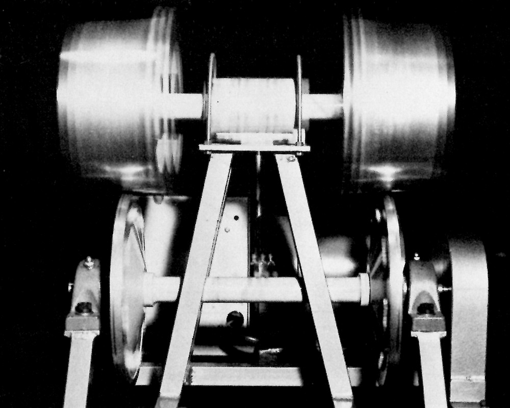
Figure 11. Instability of a model wheelset on a roller rig.
At a sufficiently higher speed, the inertia forces produced by the oscillation become dominant. In this case, creep is developed which will cause a progressive increase in the displacement of the wheelset during its lateral oscillation. Eventually, the wheelset will be restrained by the flanges or will derail.
It follows from this experiment that there is a speed at which the successive overshoots neither grow nor decay, the wheelset then, and only then, tracing out a sinusoidal path. This is termed the critical speed.
The behaviour of a wheelset sheds light on the action of a complete vehicle which must now be considered. A common type of vehicle is one in which the body is supported at each end by a bogie. Each bogie (Figure 12) consists of a frame within which is mounted two wheelsets. Now an important feature of a railway bogie is that not only is there a spring transmitting the weight of the vehicle to the wheelsets in the vertical direction, but there are springs in the longitudinal and lateral directions. It is not surprising, in view of the experiment with the model wheelset on the roller rig, that the longitudinal and lateral springs exert a major influence on the dynamic behaviour of the vehicle. However, up to recently, their importance was not recognized and in many classic designs they were effectively only provided fortuitously, by clearances and by friction. For example, in the freight vehicle suspension shown in Figure 13, which has remained unchanged in basic arrangement from about 1830 or even earlier, there is provision for vertical springing using the leaf-spring, but flexibility in other directions is only provided in a rough and ready way by the rocking of the spring from side to side and by the movement of the links.
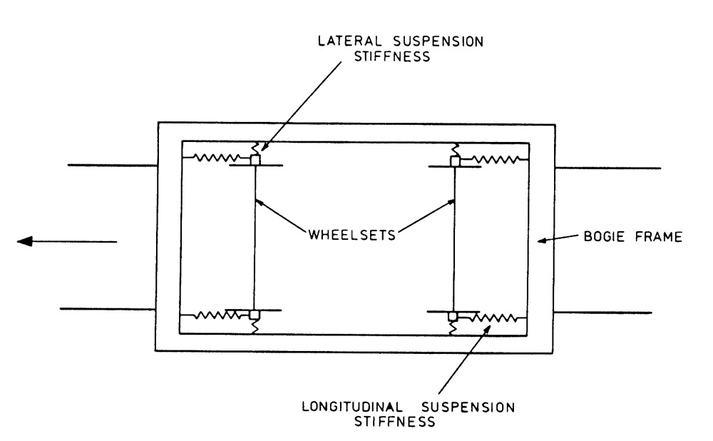
Figure 12. Plan view of a two-axle bogie showing the lateral and longitudinal suspension stiffnesses.
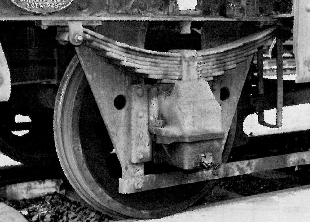
Figure 13. 'Shoe' suspension of freight vehicle.
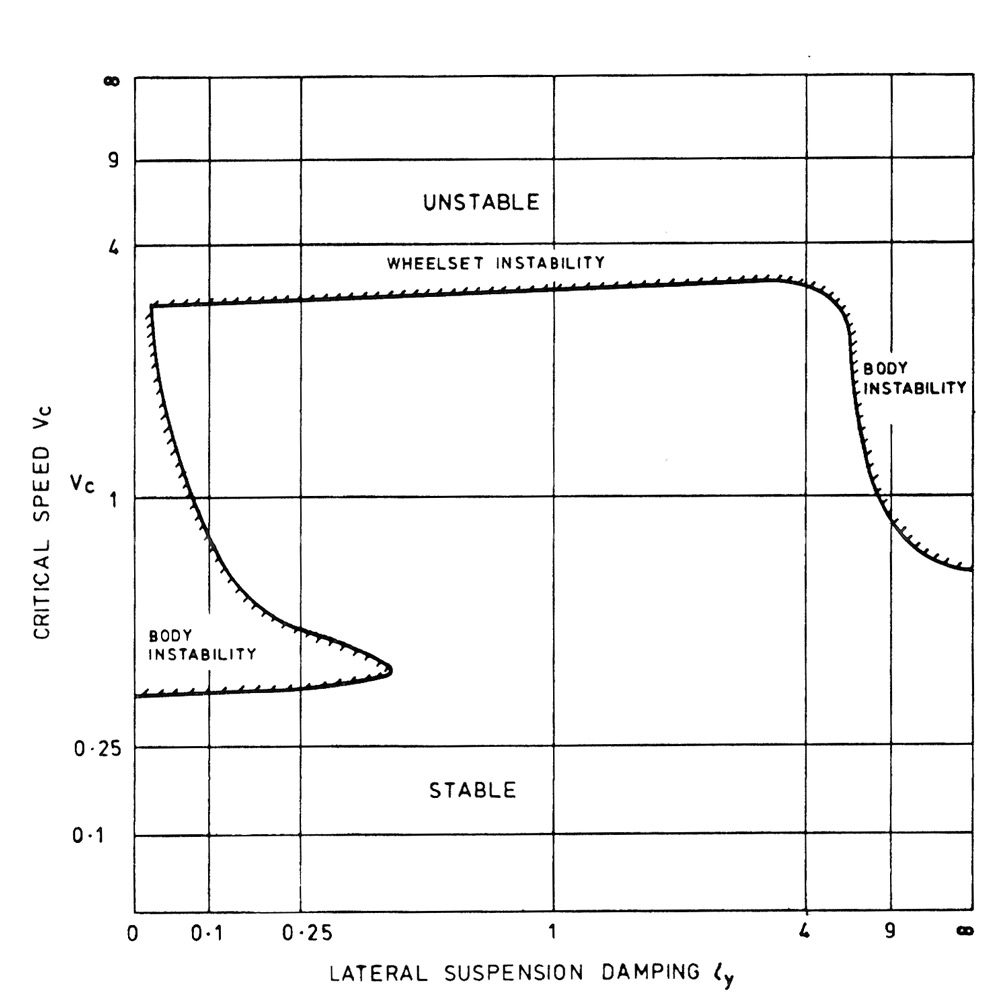
Figure 14. Stability boundary for a two-axle vehicle with flexible, damped suspension showing the relationship between vehicle speed and the lateral suspension damping (between wheelset and body)
If we apply the mathematical theory and carry out the very complex calculations that are necessary we can study the effect of varying the lateral and longitudinal suspension stiffnesses. An example of this is provided by Figure 14, where the forward speed of the vehicle is plotted along the vertical axis and the lateral suspension stiffness is plotted along the horizontal axis. The shaded area corresponds to instability - for any combination of speed and lateral suspension stiffness falling within the shaded area the lateral oscillations of the vehicle will grow until the motion is contained by the wheel flanges. The clear area corresponds to decaying oscillations and stability. The boundary which separates stability from instability corresponds to the critical speed. Now what the mathematical theory showed for the first time, and what is illustrated in Figure 14, is that the instability experienced by many vehicles at relatively low speeds could be eliminated by correct choice of the suspension parameters. For small and large values of suspension stiffness the critical speed is low and is associated with 'body hunting'. The natural oscillation of the body on the suspension is excited by the wheelset oscillation, and the resulting body oscillation is transmitted in turn by the suspension back to the wheelset, thus forming a feedback loop sustaining the oscillation. If the various parameters defining the properties of the suspension satisfy certain inequalities, then the 'body hunting' instabilities can be eliminated and the speed is then only limited by 'wheelset hunting' which occurs at a much higher speed and which is similar to the instability we saw on the model roller rig. This concept, following a series of model and full-scale laboratory experiments, found its first application in an experimental vehicle with a variable-parameter suspension, shown in Figure 15.
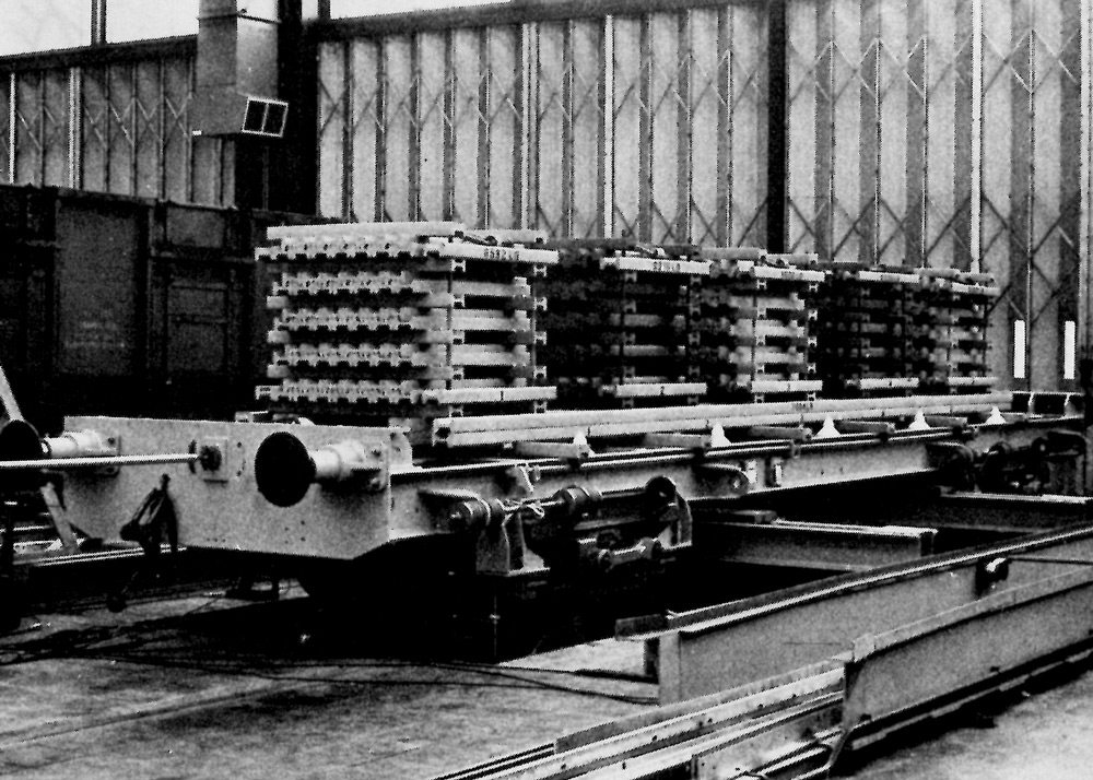
Figure 15. Experimental two-axle vehicle HSFV 1.
A second approach to suspension design is shown in Figure 16. In this case both lateral and longitudinal suspension stiffness are increased, there being an optimum at which the critical speed is a maximum. Further increases in suspension stiffness degrade stability.
Both suspension design concepts can lead to critical speeds which are very high in relation to operating speeds. However, stability is not the only criterion that must be considered.
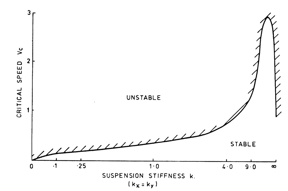
Figure 16. Stability boundary for a two-axle vehicle showing the effect of varying both the lateral and longitudinal suspension stiffness.
We have already shown that stability and guidance tend to conflict when we looked at the behaviour of a single wheelset. As we've seen already, perfect steering would be achieved if each wheelset, in a bogie or vehicle, adopted a radial position on the curve and moved out far enough so that the wheelset could roll round the curve. But, in order to meet the requirements of stability, there must be appropriate longitudinal and lateral stiffness between the wheelsets and the frame. The result is that a bogie tends to take up the attitude shown in Figure 17. Considerations of equilibrium require a departure from perfect steering and if the curve is too sharp, the wheels will slip, flange contact will be made and then guidance will be achieved largely by the flange rubbing against the rail.
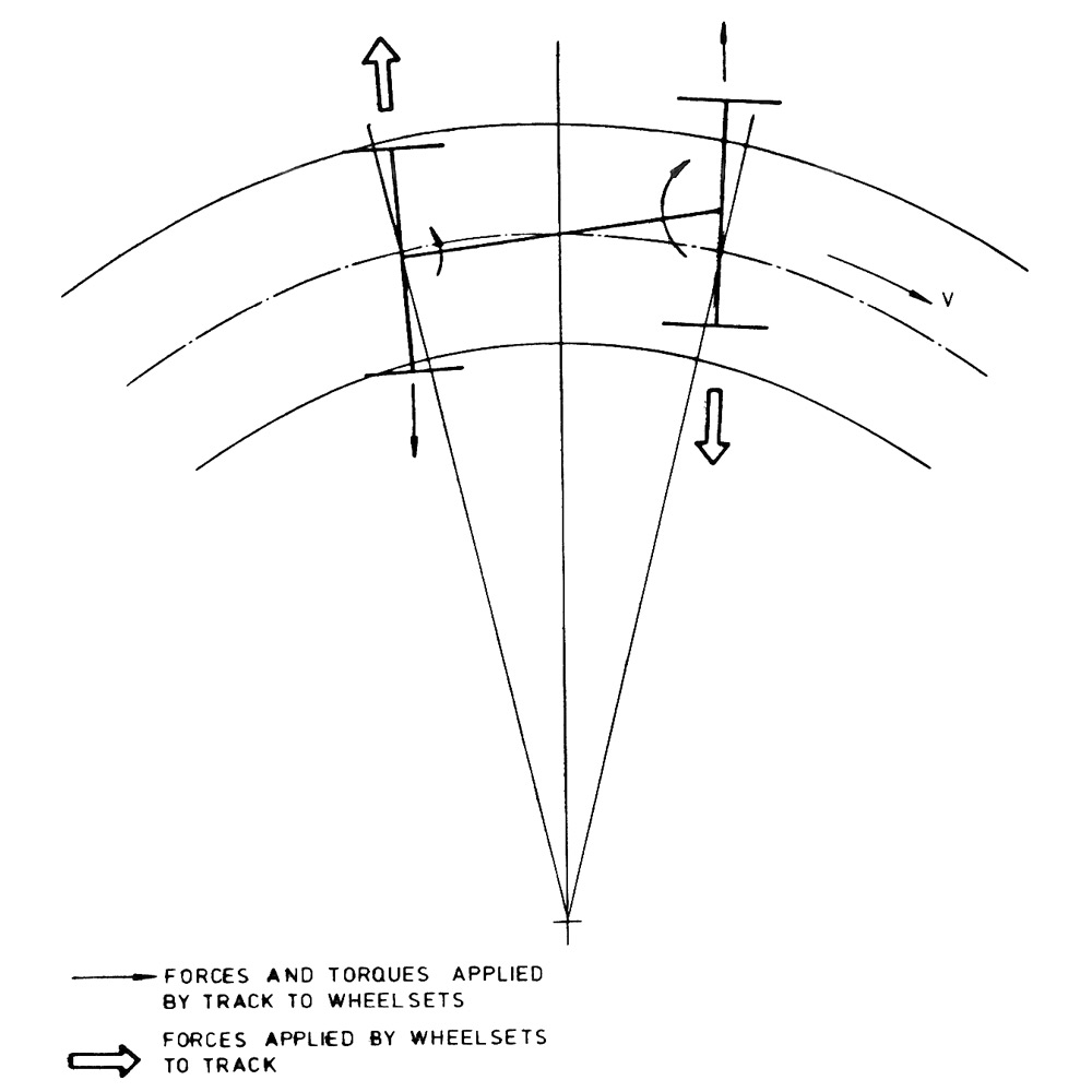
Figure 17. Attitude of a typical bogie on a curve, in plan view.
It can be shown that for a two-axle bogie perfect steering can only be obtained if the critical speed is zero. It follows that a compromise is necessary between the requirements for stability and those for curving. The resolution of this compromise is at the heart of the suspension design problem for a high speed train.
Another important aspect of the motion of railway vehicles in curves is that of passenger comfort. It is a matter of everyday experience that if you are in a vehicle that goes round a curve at too high a speed, you tend to be flung outwards and this can be uncomfortable. For a vehicle in which people not only sit but also stand or walk about, it is generally considered that the lateral acceleration should not exceed about 1/10th that of gravity. As a result railway track is canted or superelevated on curves and speed limits are then set so that lateral acceleration is within the comfort limit. Now the reduction in journey times on typical inter-city routes depends on increasing speeds, not only on the straight but also in curves. The alternative of realigning curves and thus providing a straighter railway is extremely expensive. Increasing the cant on existing curves is less expensive but is not very satisfactory for slow trains. You can imagine the reaction of people on a train that came to a halt on a curve canted at some 10° to 15°.
Apart from passenger comfort, there is a large margin of safety in curves in terms of speed. Only if this margin is exceeded is there the risk of derailment (in which a wheel flange climbs the rail) or of overturning. This was demonstrated experimentally by running a coach (modified in detail so as to represent the APT dynamically) round a curve at a succession of speeds until it either derailed or overturned. Figure 18 gives a view of such an experiment. Overturning was finally achieved on a run at a speed which gave a lateral acceleration of about 4½ times the comfort limit. At lower speeds the coach successfully negotiated the curve.
How is this very large safety margin exploited? We do, in effect, what the cyclist does. The cyclist leans into the curve so that transverse balance is achieved between the centrifugal force and the lateral component of the weight. APT has a body tilting system which is capable of tilting the body through an angle of 9°. The body in its extreme tilted positions must stay within the clearance gauge, which is set by fixed structures such as station platforms and bridge girders. Since the maximum cant of the track is about 6°, the increase in speed in a curve for the same level of passenger comfort is about 40 per cent. Figure 19 shows the experimental APT, APT-E, in the fully tilted position.
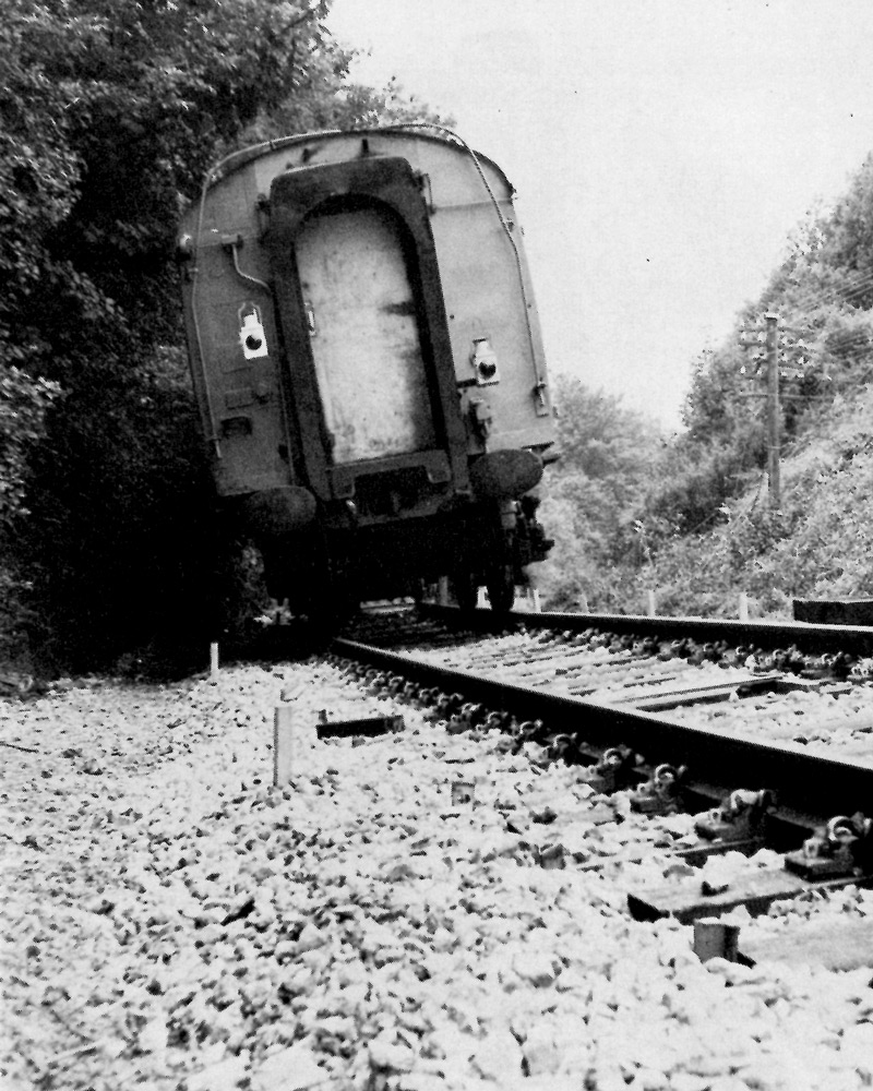
Figure 18. High cant deficiency tests on a vehicle modified to represent APT dynamically in a curve.
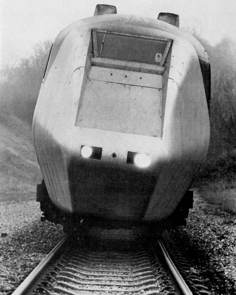
Figure 19. Experimental Advanced Passenger Train, APT-E, in tilted position.
The body is tilted by four hydraulic jacks, one at each corner of the body, mounted between the body and the bogie. Each vehicle has mounted on its body sensors which measure the lateral acceleration. The resulting signals initiate control action through a feed back servo so that the jacks are driven in a sense which tilts the body into the curve.
It is important to realize that the control system is working all the time, and the system, therefore, responds to track irregularities as well as curves. Much theoretical and experimental work has been carried out in developing the tilt system. Firstly, the performance has been optimized so that it doesn't respond so quickly that passengers can feel the angular acceleration, nor so slowly that there is inadequate cancellation of the lateral acceleration in short curves. Secondly, the system has been made reliable, so that it can be used in service without unrealistic levels of maintenance.
Whilst the tilt angles look extreme from the outside, as Figure 19 shows, the passenger only notices a slight dipping of the horizon from time to time, and as far as the passenger is concerned the tilt system converts a curvaceous railway into a straight railway.
The final aspect of the dynamics of railway vehicles to be considered is that of the dynamic response of vehicles to irregularities in the track. Railway track has about the same geometrical roughness as an airfield runway, and is much smoother than a highway. By spending a lot more on both construction and maintenance its smoothness can be improved even more. In addition to the general roughness of the track there are large, isolated defects, such as those presented by dipped rail joints, which must be considered in suspension design.
The dynamic response to track roughness is important for several reasons. Firstly, for a stable vehicle, track roughness determines the quality of ride or passenger comfort. This is usually measured in terms of the accelerations experienced by the body of the vehicle, and an important function of the suspension is to filter out the effects of track roughness. Secondly, the loads applied by the vehicle to the track are very important in determining track maintenance and, in extreme cases, the structural strength of the track. Thirdly, if the track has very large defects, then there will be loss of contact between wheels and rails and the risk of derailment.
Figure 20 shows the result of combining all these ideas into an engineering design - a bogie for APT - which is designed to achieve stability at high speed, good steering on curves, tilting, and to filter out the effects of track irregularities, imposing minimum dynamic loads on the track. Like all engineering design, there is a compromise between all the competing requirements.
A vehicle with a perfect suspension would be stable throughout the operating speed range, would negotiate curves by adopting an attitude in which the wheelsets undergo pure rolling, and would provide zero acceleration level on the body, constant forces on the track, whilst keeping suspension strokes within limits when traversing irregular track. In general, improvement in one of these respects degrades another. This is one reason why a good theory is so useful.
For example, it can be shown both experimentally and theoretically that for a two-axle bogie perfect steering on a curve requires that there be no stiffness preventing angular motion of the wheelsets relative to the frame. But if this stiffness is zero, then the critical speed is zero, and the bogie will be unstable at all speeds. Thus, a compromise is necessary in which a certain critical speed is obtained at the expense of curving ability.
Another example is given by dynamic response to irregular track. There is a conflict here between the stroke or relative displacement across the suspension and the filtering effect of the suspension. If the stroke is too large, the vehicle becomes very expensive; if it is too small then the ride is uncomfortable or worse. Zero acceleration level on the body can only be obtained by a suspension with infinite stroke. Even for the 'optimum suspension' which has the best possible performance attainable there is a minimum acceleration level, in terms of average values, for a given maximum suspension stroke. It is impossible to do better than this limit for the track roughness specified.
Furthermore, stability and response interact. Whilst a vehicle which is unstable will have unsatisfactory response, too much stability will result in high acceleration levels as well.
Thus, the basis of suspension design in APT has been to evaluate the stability, curving and response of a vehicle in terms of parameters under the control of the designer (such as the lateral and longitudinal stiffnesses of Figure 12) so as to meet performance specifications such as speed, curve radius, track roughness, passenger comfort etc. The optimization process depends on theory, and is guided by both basic theoretical results and previous experimental experience.
Let us now consider how this new approach to suspension design has been applied to APT and how it contrasts with the more conventional approach to high speed trains.
A major limitation to high speed operation of trains has always been the hunting oscillation. In Stephenson's day, two-axle vehicles were known to ride badly (in the context of present day knowledge it is clear that they had very low critical speeds amongst other shortcomings) and the adoption of long-wheelbase and bogie vehicles was stimulated by their greater lateral stability. In fact, for many years the critical speeds of bogie vehicles achieved through empirical development have not been inconsistent with maximum operating speeds. Currently, a number of countries have trains operating regularly at speeds of 200 km/h.
Typically, this has been achieved firstly by the provision of relatively high primary lateral and longitudinal suspension stiffnesses between wheelsets and bogie frame, together with a high degree of rotational restraint between the bogie frame and body, and secondly by restricting the equivalent cone angle of the wheel tread to either 1 : 20 or 1 : 40 by frequent reprofiling. Both these measures increase the critical speed significantly.
These measures, as we have already discussed, ensure that the curving performance is compromised and so in this approach to high speed train operation great emphasis is placed on good alignment of the track. This approach is very expensive as the capital costs of new or improved well-aligned tracks are very great indeed.
An alternative approach was stimulated by the development of the new techniques we have been discussing, and led to APT. This has as its objective the provision of intercity transport with reduced journey times, achieved not by expensive realignment of track but by increasing speeds in curves, and operating at speeds of up to 250 km/h on existing 160 km/h main lines.
APT exploits the suspension ideas that I have been discussing so as to make full use of the existing investment in railways. The suspensions of APT have been designed to achieve the best possible curving performance whilst retaining a margin of stability at maximum speed with fully-worn wheel profiles. The ability to operate with 'worn wheel' profiles, in addition to improving guidance in curves because the equivalent cone angle is larger, prolongs the interval between tread reprofiling and also gives lower contact stresses and reduced wear rates.
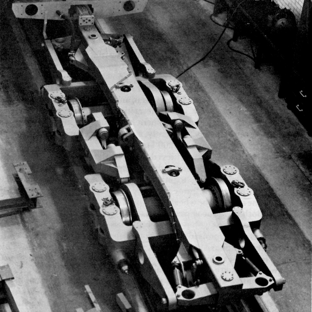
Figure 20. An articulated bogie for APT-E showing the steering beam on which the ends of two adjacent bodies are mounted, and the absence of a complete bogie frame so allowing the wheelsets freedom to steer.
Of course, APT does not consist simply of an ordinary train with a new design of bogie. The qualities of the suspension have been exploited by using lightweight aluminium alloy construction for the bodies, by using articulation to save weight and cost and by improved braking. APT combines these innovations so as to provide very high performance at substantially the same cost as that involved in providing conventional train services.
In order to develop this new technology, an experimental train, APT-E, Figure 21, was built. This train demonstrated its unique capabilities on 30 October 1975, when it ran from London (St. Pancras) to Leicester, a distance of 159 km, in 58 minutes. The fastest scheduled trains are timed to cover the distance in 1 hour 24 minutes, an average speed of 116 km/h, so that APT-E reduced the journey time by almost a third, maintaining an average speed of just over 160 km/h. Because this is a curvaceous route, this improved performance was mainly due to the higher speeds in curves of APT. On other occasions APT has demonstrated its high speed capability on straight track reaching its design maximum speed of 250 km/h.
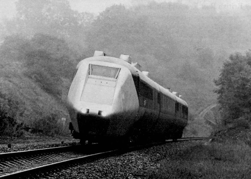
Figure 21. The articulated experimental train APT-E comprises two power cars, each powered by five automotive gas turbines with electric transmissions, and two trailer cars. One of these trailer cars is fitted with instrumentation, including on-line data processing, and the other is fitted out for subjective ride and acoustic assessment.
That the limit in speed of the steel wheel on steel rail is far from being exhausted has been demonstrated by the US Department of Transportation L.I.M. test vehicle, Figure 22, a railway vehicle running on conventional track, which has achieved a speed of 406 km/h during tests. The analysis and specification of the suspension of this vehicle was undertaken by British Rail Research under contract.
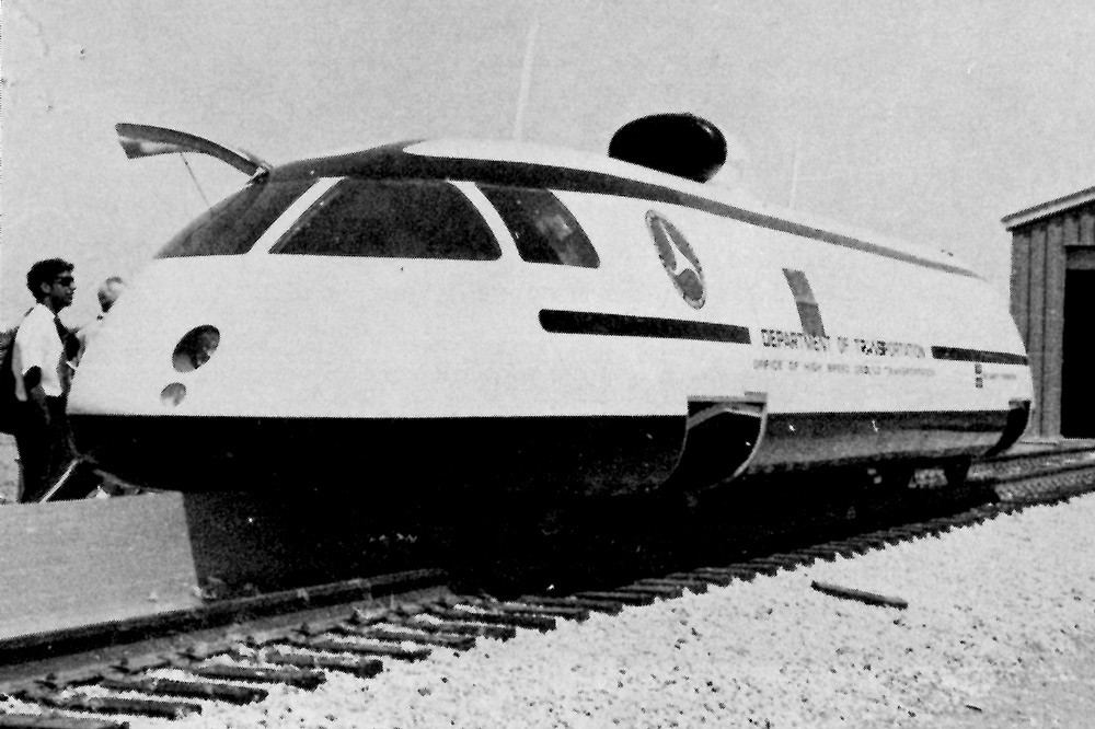
Figure 22. US Department of Transportation linear induction motor test vehicle. Whilst the propulsion system is unconventional (note the vertical reaction rail for the double-sided motor) the bogies and track are conventional in arrangement.
I hope that I have been able to show that research into the dynamics of railway vehicles has given us a good understanding of the behaviour of the coned and flanged steel wheel running on steel rails. Theory, in combination with experiment, not only tells us why certain things happen, but much more important to the engineer, it suggests innovations in design. These innovations have enabled us to improve the dynamics of trains so that, as in the case of APT, entirely new possibilities for the future of rail transport are created. As Lord Kelvin once said - 'there is nothing so practical as a good theory'.

|
|
